Snapshot of FDM Process
What is FDM (Fused Deposition Modeling)
FDM also known as Fused Deposition Modeling is a layered manufacturing process. FDM offers functional prototypes with ABS, and other materials. A thin bead of molten plastic is extruded through the computer controlled nozzle, which is deposited on a layer-by-layer basis to construct a prototype directly from 3D CAD data. The technology is commonly applied to form, fit and function analysis and concept visualisation. In addition, FDM can be used for pattern generation and rapid manufacturing.
Advantages of FDM Process
- FDM parts are strong and rigid makes them suitable for functional testing
- Cost effective solution for small to medium size parts in the shortest lead time
- Dimensional stability is a key advantage of FDM prototypes, as opposed to SLA.
- Environmental exposure does not alter the size of the parts or its features.
- Ideal for strong parts exposed to temperature, water and many chemicals.
- ABS parts can be further machined, polished or electroplated.
Applications of FDM parts
- Conceptual models for effectively evaluating, optimising and communicating your design.
- End use products without spending on tooling, moulding and machining.
- Functional FDM parts allow you to test in real world environments.
- FDM parts can be directly used for Jigs and fixtures, thermoforming tooling.
- Automotive, Aerospace companies use FDM technology to create functional and production parts.
- Product designers use FDM parts for form, fit and function analysis and concept visualisation.
- Packaging industries use FDM parts for concept designs and thermoforming tooling.
- Medical, Healthcare and Defence industries use FDM products for form, fit and functional analysis.
Finishing examples of FDM prototypes
Available Finishes
- Machine Finish
- Polished Finish
- Painted Finish
FDM ABS material specs
| Property | Data |
|---|---|
Density
|
1.05 g/cm3 |
Tensile Strength (Mpa)
|
35 Mpa |
Tensile Modulus (Mpa)
|
2000 Mpa |
Flexural Strength (MPa)
|
55 MPa |
Flexural Modulus (MPa)
|
2200 Mpa |
Heat Deflection Temp - 0.45MPa (℃)
|
72℃ |
Note: This Data is indicative only
|
|
How FDM works:
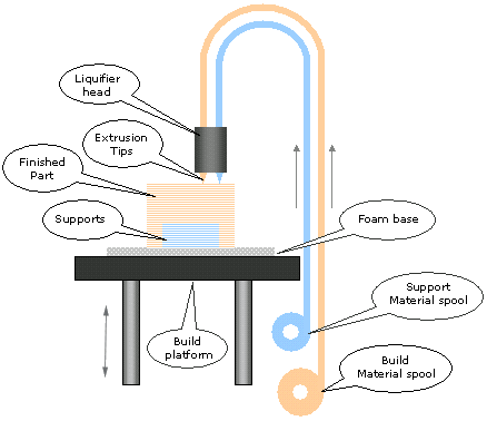
Process starts with a 3D CAD model sliced into thin layers in Z-axis. These sliced layers are used to drive an extrusion head of an FDM machine. The building material, in the form of a thin solid filament, is fed from a spool to a movable head controlled by servo motors. Second filament is fed from an adjacent nozzle for support material, used to give support for over-hanged or cantilever features. The filament reaches the liquefier head, melts it and then extruded through a nozzle onto the part surface. After covering the whole cross-section build platform descends by one layer thickness to lay down the next layer. The process repeats itself until a full 3D part is formed. The temperature of the machine chamber is precisely controlled below the melting point of the material so that only little amount of heat is required to melt the filament and on the other hand part need to be kept cool enough so that the molten material solidifies upon contact. FDM parts are suitable for strong and functional testing exposed to temperature, water or chemicals. These parts have almost 80% of the strength of injection moulded ABS material.


Limitations of FDM Process
- FDM parts have a ribbed appearance because of plastic is extruded in horizontal layers, which can be easily sanded and polished to smooth finish.
- Extensive snap features could fail due to layering process and process limitations.
- FDM could be a slower process for very large build volume parts subject to part complexity and shape. Thin wall and hollow parts are faster to make than solid builds.


